The 7 Types of Lines Used in Technical Drawing
Technical Drawing
Introduction
Technical drawing, a fundamental tool in various engineering and design disciplines, relies heavily on the use of standardized lines to convey precise information. These lines are not merely decorative; they serve specific purposes, ensuring that the drawings are universally understood and accurately interpreted. This guide delves into the seven primary types of lines used in technical drawing, exploring their characteristics, applications, and importance in creating clear and professional technical documents.
1. Continuous Line
- Description: The continuous line is the most commonly used line in technical drawing. It is a solid, unbroken line that forms the primary outlines of objects.
- Purpose: This line is used to depict the visible edges and surfaces of an object, providing a clear and direct representation of its shape and structure.
- Application: Widely used in architectural, mechanical, and electrical drawings to outline the main features of a design.
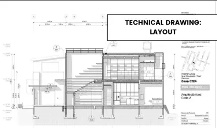
- Example: In a building plan, continuous lines are used to draw the walls, doors, and windows.
2. Dashed Line
- Description: The dashed line consists of a series of alternating dashes and gaps, creating a broken line.
- Purpose: This line is used to indicate hidden or invisible features of an object, such as internal structures or components not visible from the outside.
- Application: Commonly used in mechanical and architectural drawings to show hidden elements like beams or pipes behind a wall.
- Example: In an architectural plan, dashed lines might indicate the location of electrical wiring within a wall.
3. Dotted Line
- Description: The dotted line is a series of small, evenly spaced dots, creating a discontinuous line.
- Purpose: This line is used to represent elements that are not part of the main design but are essential for understanding the overall structure. It is often used to indicate symmetry, centerlines, or reference lines.
- Application: Frequently used in mechanical and technical drawings to denote centerlines, symmetry axes, or the location of holes.
- Example: In a mechanical drawing of an engine, dotted lines might indicate the centerline of a cylinder.

4. Chain Line (Dash-Dot)
- Description: The chain line, also known as the dash-dot line, alternates between dashes and dots.
- Purpose: This line is used to indicate the intersection of two planes or to show the material of a section in sectional views.
- Application: Commonly used in architectural and engineering drawings to denote the change in material or to indicate the plane of a section.
- Example: In a building section, chain lines might indicate the boundary between different materials, such as concrete and steel.
5. Freehand Line
- Description: The freehand line is an informal, sketchy line that is not precisely drawn.
- Purpose: This line is used in preliminary sketches and to indicate features that are not part of the final design, such as guidelines or construction lines.
- Application: Often used in the initial stages of design to quickly convey ideas and concepts.
- Example: In a sketch of a building’s facade, freehand lines might be used to indicate shading or texture.
6. Phantom Line (Alternating Dash and Dot)
- Description: The phantom line alternates between dashes and dots, similar to the chain line but with a different pattern.
- Purpose: This line is used to indicate movement, such as the path of a moving part, or to show the relationship between different components.
- Application: Commonly used in mechanical and electrical drawings to show the path of a moving object or to indicate an alternative position of a component.
- Example: In a mechanical drawing of a piston, phantom lines might indicate the movement of the piston within the cylinder.
7. Break Line
- Description: The break line is a wavy or zigzag line used to indicate that a part of the drawing is omitted for clarity.
- Purpose: This line is used to shorten a drawing by omitting a portion that is repetitive or not essential to understanding the overall design.
- Application: Frequently used in mechanical and technical drawings to break long objects or to indicate that a section is repeated.
- Example: In a drawing of a long pipe, break lines might be used to indicate that a section of the pipe is not shown.
Importance of Consistency and Standardization
Consistency in the use of these lines is crucial for ensuring that technical drawings are universally understood. Standardization allows different professionals, from architects to engineers, to interpret the drawings accurately and efficiently. Deviations from these standards can lead to confusion and errors in construction or manufacturing.
Tools and Software
Modern technical drawing relies heavily on software like AutoCAD and SolidWorks, which offer tools to create precise and standardized lines. These programs provide features that facilitate the consistent application of line types, ensuring that drawings meet industry standards.
Tips for Effective Use
- Practice: Regular practice is essential to master the drawing of these lines accurately and consistently.
- Attention to Detail: Pay close attention to the purpose of each line to ensure that the correct type is used in each context.
- Avoid Overcomplicating: Use lines sparingly and only when necessary to maintain clarity and avoid cluttering the drawing.
Case Studies
Examining real-world examples of technical drawings can provide valuable insights into the practical application of these line types. For instance, architectural plans for a residential building might use continuous lines for walls, dashed lines for hidden electrical wiring, and dotted lines for the centerlines of doors.
Conclusion
The seven types of lines used in technical drawing—continuous, dashed, dotted, chain, freehand, phantom, and break lines—are fundamental elements that ensure clarity and precision in technical communication. By understanding and correctly applying these lines, professionals can create accurate and professional technical drawings that are essential for successful project execution. Mastery of these line types, combined with adherence to standards and best practices, is key to excelling in technical drawing and its applications across various industries.
Pingback: The Instruments Used in Civil Engineering: A Comprehensive Overview – worldcivilsociety.com