Five Tools Used in Technical Drawing
Five Tools Used in Technical Drawing
Introduction
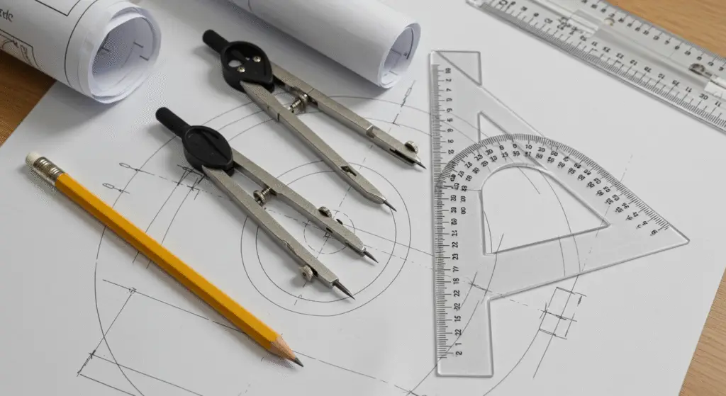
Technical drawing is a fundamental skill in various engineering and design disciplines, requiring the creation of precise and detailed technical drawings. These drawings serve as visual representations of designs, plans, and specifications, essential for conveying ideas and guiding the manufacturing and construction processes.
To achieve the necessary precision and accuracy, various tools are employed, each tailored to specific tasks in the drawing process. This guide explores five essential tools used in technical drawing, highlighting their functions, applications, and the critical role they play in producing high-quality technical documentation.
1. Pencils and Erasers
- Description: Pencils are the most basic and essential tools in technical drawing. They are used to create precise lines and details, while erasers are employed to correct mistakes or erase guidelines.
- Types of Pencils:
- Graphite Pencils: These are the most commonly used pencils in technical drawing. They are available in various hardness levels, ranging from 6H (very hard, light lines) to 6B (very soft, dark lines).
- Colored Pencils: These are used to add color to drawings, particularly in architectural and design drawings.
- Mechanical Pencils: These pencils have a fixed tip and are refilled with leads. They are ideal for technical drawing because they provide consistent line widths.
- Functions:
- Sketching: Pencils are used to create rough sketches and initial ideas.
- Detailing: They are used to add fine details and annotations to drawings.
- Erasing: Erasers are used to correct mistakes and erase guidelines.
- Applications: Pencils and erasers are essential for manual drafting, sketching, and creating preliminary designs.
- Importance: The ability to sketch and draw manually is a foundational skill in technical drawing. Pencils and erasers provide the means to explore ideas, create detailed drawings, and make necessary corrections.
2. Rulers and Straightedges
- Description: Rulers and straightedges are used to draw straight lines and measure distances. Rulers provide a straightedge for drawing lines, while straightedges ensure accuracy in aligning and drawing straight lines.
- Types of Rulers:
- Flat Ruler: A flat, flexible ruler used for drawing straight lines.
- Triangular Ruler: A rigid ruler with a triangular cross-section, often used in combination with a protractor to draw perpendicular lines.
- Scale Ruler: A ruler with graduated markings, used to measure distances and convert them into proportional representations.
- Functions:
- Drawing Straight Lines: Rulers and straightedges are used to create precise straight lines, which are essential in technical drawing.
- Measuring Distances: Rulers are used to measure the distances between points or objects in a drawing.
- Aligning Elements: Straightedges help in aligning elements in a drawing, ensuring that they are properly oriented and positioned.
- Applications: Rulers and straightedges are used in manual drafting to create accurate and precise technical drawings.
- Importance: The ability to draw straight lines and measure distances accurately is fundamental to technical drawing. Rulers and straightedges provide the means to maintain precision and consistency in drawings.
3. Protractors
- Description: Protractors are circular or semicircular instruments used to measure and draw precise angles. They are essential for ensuring that angles in drawings are accurate and consistent.
- Types of Protractors:
- Circular Protractor: A full-circle protractor, graduated from 0 to 360 degrees.
- Semicircular Protractor: A half-circle protractor, graduated from 0 to 180 degrees.
- Digital Protractor: An electronic protractor that provides digital angle measurements.
- Functions:
- Measuring Angles: Protractors are used to measure the angles between lines or objects in a drawing.
- Drawing Angles: They are used to draw precise angles, ensuring that the angles in the drawing are accurate.
- Aligning Elements: Protractors can be used to align elements in a drawing, ensuring that they are properly oriented.
- Applications: Protractors are used in technical drawing to create accurate and precise angular measurements.
- Importance: Accurate angular measurements are critical in technical drawing, particularly in mechanical and architectural drawings. Protractors provide the means to ensure that angles are represented correctly, maintaining the integrity of the design.
4. Triangles
- Description: Triangles are used to draw perpendicular and angled lines. They are essential tools in technical drawing, particularly for creating right angles and other specific angles.
- Types of Triangles:
- 45-45-90 Triangle: A right-angled triangle with two 45-degree angles.
- 30-60-90 Triangle: A right-angled triangle with angles of 30, 60, and 90 degrees.
- Adjustable Triangle: A triangle with adjustable angles, allowing for the creation of various angles.
- Functions:
- Drawing Perpendicular Lines: Triangles are used to draw perpendicular lines, ensuring that they are accurate and precise.
- Drawing Angled Lines: They are used to draw lines at specific angles, ensuring that the angles are consistent and accurate.
- Aligning Elements: Triangles can be used to align elements in a drawing, ensuring that they are properly oriented.
- Applications: Triangles are used in technical drawing to create accurate and precise angular lines.
- Importance: The ability to draw accurate angles is fundamental to technical drawing. Triangles provide the means to ensure that angles are represented correctly, maintaining the integrity of the design.
5. CAD Software
- Description: Computer-Aided Design (CAD) software is a digital tool used to create detailed 2D and 3D models. It is an essential tool in modern technical drawing, offering precision, flexibility, and the ability to collaborate effectively with stakeholders.
- Types of CAD Software:
- AutoCAD: One of the most widely used CAD software, known for its versatility and precision.
- SolidWorks: A 3D CAD software used for creating complex mechanical designs.
- Revit: A BIM (Building Information Modeling) software used for architectural and engineering designs.
- Functions:
- Creating 2D and 3D Models: CAD software is used to create detailed 2D and 3D models of designs.
- Simulating Designs: It allows for the simulation of designs, enabling engineers to test and analyze the behavior of structures and components.
- Collaborating: CAD software facilitates collaboration among stakeholders, allowing for the sharing and reviewing of designs.
- Applications: CAD software is used in technical drawing to create precise and detailed designs, simulate behavior, and collaborate with stakeholders.
- Importance: CAD software has revolutionized technical drawing, offering unprecedented precision, flexibility, and efficiency. It is an indispensable tool in modern engineering and design, enabling the creation of complex and detailed designs with ease.
Importance of Tools in Technical Drawing
The tools used in technical drawing are essential for creating precise and accurate technical drawings. Each tool serves a specific purpose, and the effective use of these tools is critical to the success of engineering and design projects. By understanding and mastering these tools, engineers and designers can create high-quality technical drawings that convey their ideas clearly and accurately.
Tips for Effective Use
- Practice: Regular practice is essential to master the use of these tools. The more you practice, the more comfortable and proficient you will become in using them.
- Attention to Detail: Pay close attention to the details of your drawing. Ensure that lines are precise, angles are accurate, and measurements are correct.
- Use of Guidelines: Use guidelines and construction lines to help you draw accurately. These lines can be erased later, but they provide a foundation for your drawing.
- Selection of Tools: Choose the right tool for the task. For example, use a pencil for sketching and a pen for final drawings.
- Erasing: Use erasers to correct mistakes and erase unnecessary lines. A clean drawing is easier to read and understand.
Case Studies
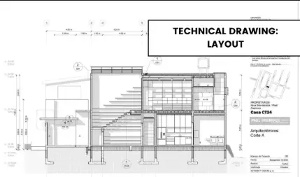
Examining real-world examples of technical drawings can provide valuable insights into the practical application of these tools. For instance, architectural plans for a residential building might use pencils and erasers for sketching, rulers and straightedges for drawing straight lines, protractors for measuring angles, triangles for drawing perpendicular lines, and CAD software for creating detailed 2D and 3D models.
Emerging Technologies
The field of technical drawing is continually evolving, with emerging technologies offering new possibilities for improving the design and manufacturing processes. Some of these technologies include:
- 3D Printing: Used to create physical prototypes of designs, allowing for the visualization and testing of products.
- Laser Scanning: Used to create detailed 3D models of objects and environments, providing accurate measurements and representations.
- Augmented Reality (AR) and Virtual Reality (VR): Used to visualize and interact with digital models, enhancing the design and collaboration process.
Conclusion
The five tools discussed in this guide—pencils and erasers, rulers and straightedges, protractors, triangles, and CAD software—are essential for creating precise and accurate technical drawings. Each tool serves a specific purpose, and the effective use of these tools is critical to the success of engineering and design projects.
By understanding and mastering these tools, engineers and designers can create high-quality technical drawings that convey their ideas clearly and accurately. As technology continues to advance, the array of tools available to engineers will undoubtedly expand, offering even greater precision and capabilities. However, the fundamental principles of technical drawing remain unchanged, and the ability to use these tools effectively will always be a valuable skill in the engineering and design professions.
Pingback: The Three Main Types of Technical Drawing: A Comprehensive Guide – worldcivilsociety.com