Did you know that mechanical engineers use a vast array of tools to design, develop, and test their projects? From complex simulations to precise measurements, these essential tools enhance productivity and product quality. With the right tools, engineers can streamline their workflow and focus on innovation.
By leveraging the right mechanical engineering essentials, professionals can achieve higher design efficiency and faster production times. This not only benefits the engineers but also contributes to the overall success of their projects.
Key Takeaways
- Mechanical engineers rely on a wide range of tools for their projects.
- The right tools enhance productivity and product quality.
- Essential tools include design software, simulation tools, and measurement devices.
- Streamlining workflow allows engineers to focus on innovation.
- Higher design efficiency and faster production times are achieved with the right tools.
Introduction to Mechanical Engineering Tools
Mechanical engineering encompasses a broad range of tools that are essential for product development. These tools have evolved significantly with advancements in manufacturing technologies, especially in handling smaller parts and tighter tolerances.
As manufacturing technologies advance, especially with the challenges of smaller parts and tighter tolerances, it is more important than ever to have handheld and digital tools that provide the speed and high precision that mechanical engineers require. The right tools not only enhance productivity but also ensure the quality and reliability of the products being developed.
Importance of the Right Tools
Having the right tools is crucial for mechanical engineers to innovate and produce high-quality products. According to a guide on tools that every mechanical engineer should, the selection of appropriate tools can significantly impact project outcomes.
The importance of the right tools can be seen in several areas:
- Precision: Tools that offer high precision help in achieving the desired product specifications.
- Efficiency: The right tools can significantly reduce production time, enhancing overall efficiency.
- Innovation: Advanced tools enable mechanical engineers to innovate and explore new product designs and functionalities.
Overview of Common Tools
Mechanical engineers utilize a variety of tools, ranging from CAD software to measurement instruments. For a comprehensive understanding of the branches of engineering and the tools involved, visiting resources like branches of engineering can be beneficial.
Some of the common tools include:
| Tool Category | Examples | Application |
|---|---|---|
| CAD Software | SolidWorks, AutoCAD | Design and drafting |
| Simulation Software | ANSYS, Simulink | Testing and validation |
| Measurement Instruments | Caliper, Micrometer | Quality control and inspection |
The table above highlights some of the essential tools used in mechanical engineering, showcasing their categories, examples, and applications. By leveraging these tools, mechanical engineers can ensure that their projects are executed with precision and efficiency.
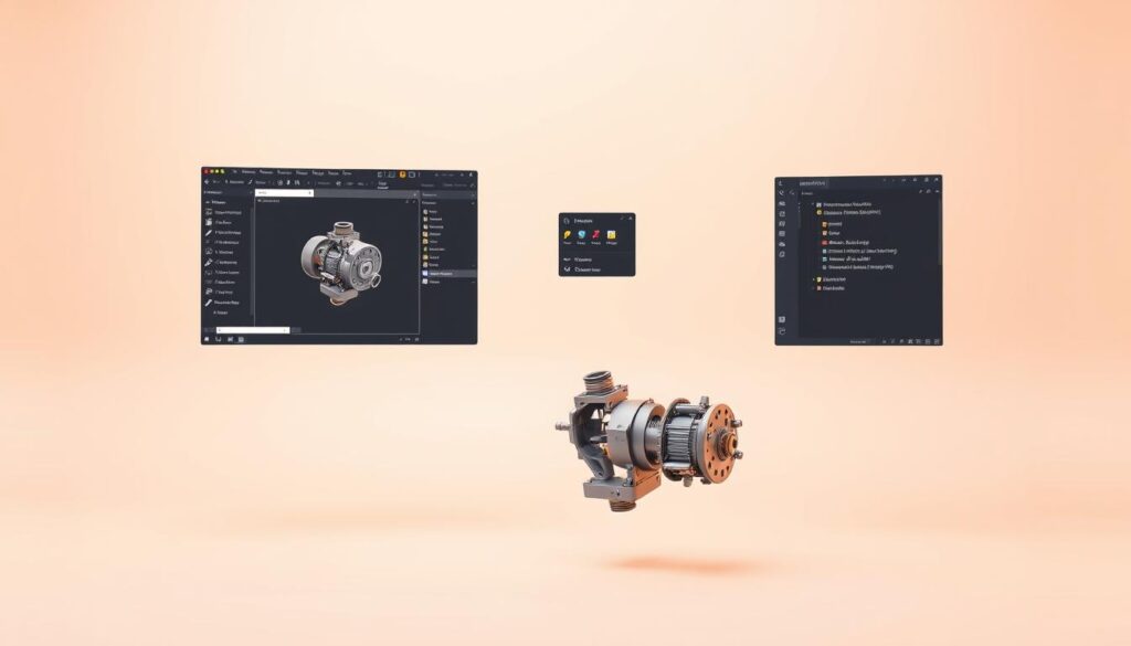
CAD Software for Design

CAD software is a cornerstone of modern mechanical engineering, enabling designers to create precise and complex designs. It has become a must-have tool for mechanical engineers, allowing them to work efficiently and effectively.
To get the most out of CAD software, it’s essential to understand its capabilities and how to use it efficiently. One tip is to utilize keyboard shortcuts, which can significantly speed up the design process.
Examples of Popular CAD Tools
Several CAD software options are widely used in the industry. Some of the most popular include:
- SolidWorks
- Autodesk Inventor
- CATIA
- Fusion 360
For those looking to learn more about using CAD software, resources like CAD tutorials can be incredibly helpful.
Benefits of Using CAD Software
The benefits of CAD software are numerous. It allows for precise design, reduced errors, and increased productivity. Here’s a comparison of some key benefits:
| Benefit | Description | Impact |
|---|---|---|
| Precision | Accurate designs with minimal errors | Reduces costly revisions |
| Productivity | Streamlined design process | Increases efficiency and speed |
| Collaboration | Easy sharing and collaboration | Enhances teamwork and communication |
CAD software has revolutionized the design process, making it an indispensable tool for mechanical engineers. By understanding its capabilities and using it efficiently, engineers can create innovative products with precision and accuracy.
Simulation Software for Testing
The use of simulation software in mechanical engineering has revolutionized the design testing process, enhancing both efficiency and accuracy. Simulation software allows engineers to test the structural integrity of their designs virtually, reducing the need for physical prototypes and thereby saving time and resources.
Variety of Simulation Tools
There are various types of simulation tools available, catering to different aspects of mechanical engineering. Some of the most commonly used include:
- Finite Element Analysis (FEA) tools like Ansys and Abaqus, which are used to analyze the structural integrity of designs under various conditions.
- Computational Fluid Dynamics (CFD) tools, which simulate the behavior of fluids and gases around and through designs.
- Multi-body Dynamics (MBD) tools, used for simulating the motion and interaction of multiple bodies in a system.
Enhancing Design through Simulations
Simulations significantly enhance the design process by allowing engineers to test and validate their designs under various conditions without the need for physical prototypes. This not only reduces costs but also accelerates the development process. Through simulations, engineers can:
- Identify potential design flaws early in the development process.
- Optimize designs for better performance and efficiency.
- Reduce material waste by minimizing the need for physical prototypes.
By leveraging simulation software, mechanical engineers can ensure that their designs are robust, efficient, and meet the required specifications, ultimately leading to better products and reduced development times.
CAM Software for Manufacturing

The role of CAM software in modern manufacturing cannot be overstated, as it bridges the gap between design and production.
CAM (Computer-Aided Manufacturing) software plays a crucial role in production by automating the manufacturing process. It works in conjunction with CAD software to ensure efficient production. This integration enables mechanical engineers to design and manufacture products seamlessly.
Role of CAM in Production
CAM software automates the manufacturing process by generating G-code from CAD designs, which is then used to control machine tools. This automation enhances precision, reduces production time, and increases overall efficiency.
The use of CAM software in production also allows for:
- Improved accuracy and precision
- Reduced material waste
- Increased productivity
- Enhanced design complexity
Leading CAM Software Options
Several CAM software options are available, catering to different needs and complexities. Some of the leading options include:
| Software | Description | Key Features |
|---|---|---|
| Mastercam | A comprehensive CAM software for milling, turning, and wire EDM. | Dynamic toolpaths, solid model machining |
| Autodesk Fusion 360 | A cloud-based CAD/CAM software for 3D modeling and machining. | Integrated CAD/CAM, cloud collaboration |
| GibbsCAM | A CAM software for CNC programming, offering various machining capabilities. | Multi-axis machining, solid modeling |
By leveraging these CAM software options, mechanical engineers can significantly enhance the manufacturing process, leading to improved product quality and reduced production costs.
Finite Element Analysis (FEA) Tools
Understanding the capabilities of Finite Element Analysis (FEA) tools is essential for optimizing product design and performance. FEA helps engineers determine how a product will react to real-world stresses, enabling them to make informed decisions during the design process.
Basics and Applications
FEA is a computational method used for simulating physical phenomena under various types of loads. It’s widely used in mechanical engineering to analyze stress, strain, and vibration in complex systems. The applications of FEA are vast, ranging from analyzing structural integrity to simulating thermal and fluid dynamics.
- Structural Analysis: FEA helps in understanding how structures respond to different loads.
- Thermal Analysis: It simulates how temperature changes affect product performance.
- Vibration Analysis: Engineers use FEA to predict how products will behave under vibrational forces.
Top FEA Software to Consider
Several FEA software options are available, catering to different needs and complexities. Some of the top FEA software includes:
- ANSYS: Known for its comprehensive simulation capabilities.
- Autodesk Inventor: Offers robust FEA tools integrated within its CAD environment.
- Other notable FEA software includes Abaqus, Nastran, and LS-DYNA.
Selecting the right FEA tool depends on the specific requirements of your project, including the type of analysis, complexity, and integration with other engineering tools.
3D Printing and Additive Manufacturing

3D printing and additive manufacturing are transforming the way mechanical engineers design and develop prototypes. This technology has revolutionized the field by enabling rapid prototyping, improving design accuracy, and reducing the need for multiple iterations.
Impact on Engineering
The impact of 3D printing on engineering is multifaceted. It enhances prototype development by saving time, improving design precision, and reducing material waste. According to best practices in 3D printing, engineers can now create complex geometries that were previously impossible or too costly to produce.
Key benefits include:
- Rapid prototyping
- Improved design accuracy
- Reduced material waste
- Enhanced product customization
Recommended 3D Printing Tools
Several software programs are highly recommended for 3D printing, including Fusion360, Solid Edge, Tinkercad, and OnShape. These tools offer a range of features that cater to different aspects of 3D printing, from design to manufacturing.
For those interested in exploring the best type of engineering, further resources are available that discuss the various disciplines within engineering.
By leveraging these top tools for mechanical engineers, professionals in the field can significantly enhance their productivity and innovation capabilities.
Computational Fluid Dynamics (CFD) Tools
In the realm of mechanical engineering, CFD tools play a crucial role in analyzing and optimizing systems that involve fluid dynamics. These tools enable engineers to simulate the behavior of fluids and gases under various conditions, leading to more efficient and effective designs.
CFD tools are essential equipment for mechanical engineers, allowing them to predict how fluids will interact with different components of a system. This predictive capability is invaluable in designing systems that require precise control over fluid flow and heat transfer, such as pipelines, pumps, and heat exchangers.
Understanding CFD and Its Uses
CFD involves the numerical analysis of fluid flow, heat transfer, and mass transport. By solving the equations that govern these phenomena, CFD tools provide detailed insights into the behavior of complex systems. This information is used to optimize system performance, reduce energy consumption, and enhance safety.
The applications of CFD are diverse, ranging from aerospace and automotive engineering to chemical processing and energy production. For instance, in the aerospace industry, CFD is used to optimize the aerodynamics of aircraft, while in the chemical industry, it is used to design more efficient reactors and mixing systems.
Popular CFD Software Choices
Several CFD software packages are widely used in the industry, each with its strengths and specializations. Some of the most popular choices include:
- ANSYS Fluent
- OpenFOAM
- COMSOL Multiphysics
- STAR-CCM+
These software tools offer advanced features such as turbulence modeling, multiphase flow simulation, and conjugate heat transfer analysis. The choice of software depends on the specific requirements of the project, including the complexity of the problem, the desired level of accuracy, and the available computational resources.
| Software | Key Features | Applications |
|---|---|---|
| ANSYS Fluent | Turbulence modeling, multiphase flow | Aerospace, automotive, chemical processing |
| OpenFOAM | Open-source, customizable | Research, complex simulations |
| COMSOL Multiphysics | Multiphysics simulations, user-friendly interface | MEMS, biomedical, energy |
Project Management Tools

The use of project management tools has become indispensable in mechanical engineering for ensuring project success. These tools help in organizing tasks, tracking progress, and facilitating communication among team members.
Streamlining Project Execution
Effective project management is critical in mechanical engineering to meet project deadlines and stay within budget. Project management tools enable engineers to plan, coordinate, and monitor their projects efficiently. For instance, tools like Asana, Trello, and MS Project are widely used for their versatility and user-friendly interfaces.
By utilizing these tools, mechanical engineers can enhance collaboration among team members, reduce misunderstandings, and improve overall project productivity.
Key Software for Project Tracking
Several software options are available for project tracking, each offering unique features that cater to different project needs. For example, software for project engineers can provide specialized functionalities that are beneficial for mechanical engineering projects.
- Asana: Ideal for task management and team collaboration.
- Trello: Offers a visual approach to project management using boards and cards.
- MS Project: Provides comprehensive project planning and tracking capabilities.
By selecting the right project management tool, mechanical engineers can significantly improve their project’s outcome, ensuring it is completed on time and within the allocated budget.
Measurement and Inspection Tools
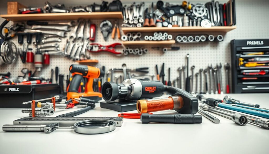
Mechanical engineers rely on a variety of measurement and inspection tools to ensure the quality and accuracy of their projects. These tools are crucial in verifying that components meet specifications and tolerances, ultimately affecting the performance and reliability of the final product.
Essential Measurement Instruments
Some of the most commonly used measurement instruments include calipers, micrometers, and coordinate measuring machines (CMM). Calipers are versatile tools used for measuring the distance between two opposite sides of an object. Micrometers offer high precision for measuring small dimensions. CMMs are sophisticated devices that use a probe to measure the geometry of physical objects.
For a more comprehensive list of measuring instruments, you can refer to resources like 30 Measuring Instruments for Mechanical Engineers, which provides an extensive overview of tools used in the field.
Advances in Measurement Technology
Recent advancements in measurement technology have led to the development of more accurate and efficient tools. For instance, optical measurement techniques and laser scanning have improved the precision of dimensional measurements. These technologies enable engineers to inspect complex geometries and detect minute deviations from specifications.
The integration of advanced measurement tools into mechanical engineering practices not only enhances product quality but also streamlines the manufacturing process. By ensuring that components are accurately measured and inspected, engineers can reduce errors and improve overall efficiency.
Collaborative Design Tools

Effective collaboration is crucial in mechanical engineering, and the right tools can make all the difference. In today’s complex design environments, teams need to work together seamlessly to bring projects to life.
Teamwork Makes the Dream Work
The importance of team collaboration cannot be overstated. When engineers work together effectively, they can share ideas, identify potential issues, and develop innovative solutions. Collaborative design tools enable teams to work together more effectively by providing a centralized platform for project files, communication, and task management.
Platforms like Vistapoint PDM facilitate collaboration by providing a single source of truth for project data. This ensures that all team members are on the same page, reducing errors and miscommunication.
Best Collaborative Workspaces
So, what makes a great collaborative workspace? Here are some key features to look for:
- Real-time commenting and feedback: Allows team members to provide instant feedback on designs.
- Version control: Ensures that everyone is working with the latest version of a design file.
- Task assignment and tracking: Enables project managers to assign tasks and track progress.
- Integration with other tools: Seamlessly integrates with other design and project management tools.
Some of the top collaborative design tools for mechanical engineers include:
- Vistapoint PDM
- Autodesk Fusion Team
- Siemens Teamcenter
By leveraging these collaborative design tools, mechanical engineers can work more efficiently, reduce costs, and deliver high-quality projects on time.
Prototyping Tools and Techniques
Prototyping tools and techniques have revolutionized the way mechanical engineers design and develop new products. By enabling the creation of functional prototypes, these tools facilitate testing, validation, and refinement of designs before they move to production.
Different Prototyping Methods
There are various prototyping methods that mechanical engineers can utilize, depending on the project’s requirements. 3D printing is a popular choice for rapid prototyping, allowing for the quick creation of complex geometries. Other methods include CNC machining, laser cutting, and traditional model making.
Each method has its advantages and is suited for different stages of the design process. For instance, 3D printing is ideal for creating complex internal structures, while CNC machining is better suited for producing parts that require high precision and surface finish.
Tools for Effective Prototyping
To effectively prototype, engineers rely on a range of tools and software. For a comprehensive guide on prototyping tools, visit Formlabs’ guide to prototyping tools. Some of the key tools include:
- CAD software for designing prototypes
- 3D printing technology for rapid prototyping
- CNC machining for precision parts
- Simulation software for testing prototype performance
| Prototyping Method | Advantages | Applications |
|---|---|---|
| 3D Printing | Rapid creation, complex geometries | Complex internal structures, rapid prototypes |
| CNC Machining | High precision, good surface finish | Precision parts, functional prototypes |
| Laser Cutting | High accuracy, fast processing | Thin parts, detailed designs |
By leveraging these prototyping tools and techniques, mechanical engineers can significantly enhance the product development process, reducing time-to-market and improving product quality.
Electrical Engineering Tools for Mechanical Engineers

In today’s interdisciplinary engineering landscape, mechanical engineers must be equipped with the right electrical engineering tools to succeed. As projects become increasingly complex, the need for tools that can bridge the gap between mechanical and electrical engineering is more pressing than ever.
Interdisciplinary Tools
Mechanical engineers working on projects that involve electrical engineering can greatly benefit from using interdisciplinary tools. One such tool is MATLAB, which is widely used for its ability to integrate mechanical and electrical engineering principles. MATLAB allows engineers to model and simulate complex systems, making it an indispensable tool for interdisciplinary projects. For more insights on tools that every mechanical engineer should know, visit ASME.
Another valuable tool is Visual Basic for Applications (VBA), which can be used to automate tasks and enhance the functionality of software applications used in both mechanical and electrical engineering. VBA’s versatility makes it a powerful tool for engineers looking to streamline their workflow.
Tools for Integrated Design
When it comes to integrated design, mechanical engineers need tools that can seamlessly integrate electrical engineering aspects. Mechatronics engineering is a field that combines mechanics, electronics, and computing, and tools like Simulink are crucial for designing and simulating mechatronic systems. For a deeper dive into mechatronics engineering, check out World Civil Society.
| Tool | Description | Application |
|---|---|---|
| MATLAB | High-level programming language for numerical computation | Modeling and simulating complex systems |
| VBA | Programming language for automating tasks in software applications | Enhancing software functionality and workflow automation |
| Simulink | Graphical programming language for modeling and simulating complex systems | Designing and simulating mechatronic systems |
By leveraging these tools, mechanical engineers can enhance their capabilities and deliver projects that meet the demands of modern engineering. Whether it’s through modeling complex systems or automating tasks, the right tools can make a significant difference in the success of a project.
Continuing Education and Resources
Staying updated with the latest engineering tools every mechanical engineer should know is crucial in today’s fast-paced mechanical engineering landscape. As technology advances, mechanical engineers must continually update their skills to remain relevant.
Ongoing Learning
Mechanical engineers can benefit from various online courses and books that focus on mechanical engineering tools and their applications. These resources help engineers expand their knowledge and stay current with industry developments.
Recommended Resources
Online platforms like Coursera, edX, and Udemy offer a wide range of courses on mechanical engineering and related tools. Books such as “Mechanical Engineering Design” and “Introduction to Mechanical Engineering” provide foundational knowledge. Familiarity with these resources can help mechanical engineers enhance their skills in using various mechanical engineering tools.
